I’d recommend reading the
“operation” section of the SPI wiki: https://en.wikipedia.org/wiki/Serial_Peripheral_Interface
Just a quick heads up:
- DO (data out), SDO (serial data out), MOSI (master out, slave in) all mean the same thing
- DI (data in), SDI (serial data in), MISO (Master In, slave out) all mean the same
- /CS (chip select), /SS (slave select), nCS, nSS all mean the same thing
- Both ‘n’ and ‘/’ mean the signal is active low, not active high
The basic concept of SPI is that
the master initiates every communication. Also one bit is sent by both the
master and the slave on every clock edge.
Say you want to read two pieces of
data from the slave, you can chain commands together.
MOSI
[Read command 1] [Read
command 2] [don’t care]
MISO
[don’t
care]
[Response 1]
[Response 2]
Note the slave can’t respond
until it’s received all of command 1. In this example, command 2 provides
the clock edges for the slave to respond with.
At the end, the master must
clock an additional packet in (the don’t care above) to get the final response
out.
Moving up the chain in
complexity is independent slaves:
The clock, MOSI and MISO lines
are shared. Each slave has a chip select (/SS) and responds when
addressed.
Moving up the chain again is
daisychained slaves.
If I want to talk to green, I
feed one packet in to write the command. Green sends its response to blue,
and blue sends its response to purple, and purple to master.
If you want, you can command all three at once, but you’ll need to send a bunch of don’t care data to flush the
shift register and make sure Blue doesn’t try and use green’s response as a
command.
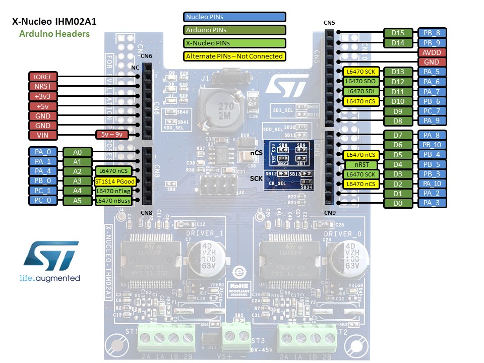
Looking at the Nucleo schematic, you’ll notice L6470_1_SDO (Serial Data Out) is connected to
L6470_0_SDI (Serial Data In). This is a daisy chain configuration. Also note how the bridging SB7 leads to the D2 pin on the board.
Looking at the part datasheet,
it will start reading data when /CS is low, and will keep shifting data out
until /CS is high.
By stacking a second board, this configuration results—it’s a combination of both the daisy chain
and individually addressed version above:
Motor 1 and 2 move, so nCS1 is working.
Probing nSS2dd with the scope—should jump between 5v to 0v
All four nCS's are connected in the middle (as shown on the right in red).


No comments:
Post a Comment