Needed now?
- MOSFET power models in Spice
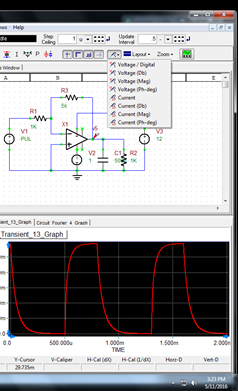
Probes
Voltage/Digital regular ~ used most often
Voltage (Db) gains of amplifiers, attenuation of signals, and signal-to-noise ratios
Voltage (Ph-deg) not used, esp. not used in transient
Current ~ used most often
Current (Db) gain, attenuation, and signal-to-noise ratios often expressed in decibels
Current (Mag) forget about this
Current (Ph-deg) don’t worry about this
- The same for current, the main choice boils down to either “Voltage/Digital” or “Voltage (Mag).”
Tests (basic)
- Transient - time graphs ~ pulse waveform input, switching or step functions (similar modeling)
- Real equal (critically damped) and complex (under damped) offshoots are normal. In other words, offshoots from second order and higher circuits can go over the maximum input waveform. (See Transient Analysis Quick Review.)
- Linearize Step
- Automatically set at 1/50 simulation run time
- If doubtfull graph, half the time for smoother or improved results

- DC Bias - node or component values (B2 Spice Introduction Part I & Part II) ~ mostly just for Circuits I
- AC Bias - frequency response, which usually needs to be switched to a logarithmic graph
- Edit Axis
- Drop-down menu: Bottom Axis
- Check logarithmic
- Transient - oscilloscope graph ~ Circuits II; this video also goes with AC Bias
- Setting the Stop Time
- 1/T (inverse period)
- allowing for 3-4 periods: demo. (same as previous hyperlink)
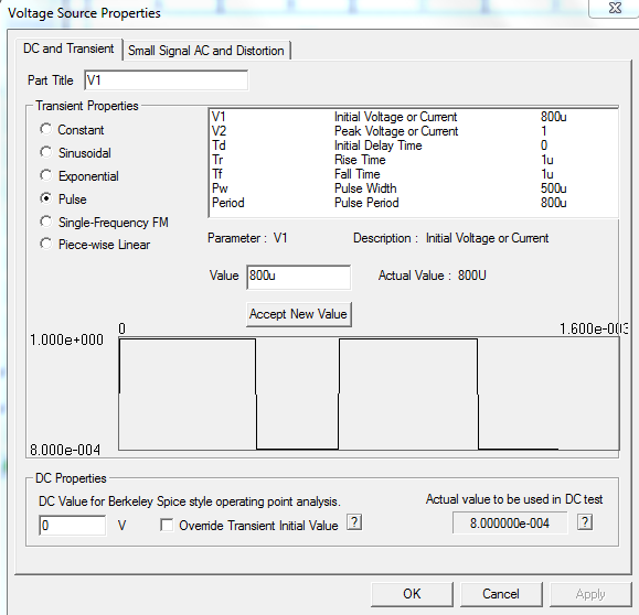
Voltage Source Properties (click on the source)
DC and Transient - transient analysis = large signal analysis ~ most analyses
Small Signal AC and Distortion - AC analysis ~ details
Common imperfections of physical devices (source: http://spicesim.blogspot.com/p/how-to-think-like-spice.html)
Resistors
inductance for wirewound resistors
Capacitors
series resistance, especially electrolytics where resistance is large and varies strongly with frequency and temperature. Also far from perfect are ceramic caps made from high dielectric materials (Z5u, etc.).
Inductors, transformers
series resistance, self resonance with the winding capacitance (at surprisingly low frequencies) and usually a series resonance at much higher frequency. If there is a magnetic core, it may saturate and has losses that go up very rapidly with frequency.
Spice model limitation at High Frequency / fast rise time
The general purpose Spice models (.Model) for diodes, FETs and transistors do not include any lead inductance. You or the manufacturer can write a Spice .Subckt which contains the .Model plus lead/package inductances. Power MOSFETs are modeled using a .Subckt and usually have these inductances.
Switching circuits with inductors/transformers
The inductors and transformers in Spice have no winding capacitance. Switching an ideal inductor that has current flowing can result in an infinite voltage spike with zero rise time. Simulation will fail (you can almost feel the simulated gamma rays coming out of the screen). Add parallel capacitance and/or resistance to limit bandwidth and limit spike rise time/amplitude during switching.
Power supplies
Spice voltage sources turn on instantly. Real power supplies do not. This sometimes results in Spice finding a different DC Bias solution than the actual circuit has!
Spice voltage sources have such low impedance over all frequencies that they will short out DC drop, ripple and noise that would appear in any real world circuit. Consider adding series resistance (and possibly inductance).
Source: http://spicesim.blogspot.com/p/how-to-think-like-spice.html
Op-amps
Goomey's basic setup of both AC and transient analysis
Minor details

Op-amps
Goomey's basic setup of both AC and transient analysis
Minor details
- Color
- click graph
- Edit Plot (See upper left corner of picture:)
- more in detail about the different tests
- virtual instruments
- Virtual Bode Plotter
- virtual voltmeter sometimes needed because something wrong with probes